Thursday, October 6, 2016

Arcade Machine

My latest project is to build an arcade machine, well, more accurately an arcade emulator.


The whole rig is built around a Raspberry pi (rpi), which I conveniently had lying around. This is actually a first generation board, but with some minor tweaking worked quite well.

I started off with the latest Raspbian build, the official Debian based OS. Next I installed the most excellent arcade emulator, MAME, Multiple Arcade Machine Emulator.

The rpi has 15 available general purpose input output (GPIO) lines, which can be used for almost anything. (Further IO are available, but not without sacrificing some functionality). I wanted to be able to play with my buddies, so I opted for a two player setup. For each player, I use 4 lines for the joystick and 2 lines for action buttons. I use further two lines for 1 player and 2 player buttons, and one for credit/coin. That's 15 all together.


No other work is required but tieing the GPIO to ground, and a button press will short that GPIO to ground. No resistors or anything, just some minor soldering.


To use the GPIO in MAME, that is, the joystick and the buttons, I emulate a USB keyboard. So, when a button is pressed, a corresponding keyboard input is triggered. To do this, I use Adafruits retrogame tool. The code is open and available. All I had to do is to map the additional inputs in wanted to use to the right keyboard function. One word of warning: if you like me are not using one of their external interface boards (called HATs), you must change a 0 to a 1 in in the routine where it selects it's board, or else you will get an error where the program will try to access unavailable GPIO.

Another thing I had to do is to over clock the CPU to 900 MHz, to make things run smoother (no frame drops).

Conveniently, there are also 3.3V and 5V lines exposed, so I can light up my buttons too!

So there you have it! I'm now onto building the actual cabinet.


Thursday, July 21, 2016

Solar Rechargeable Pocket Flashlight Teardown

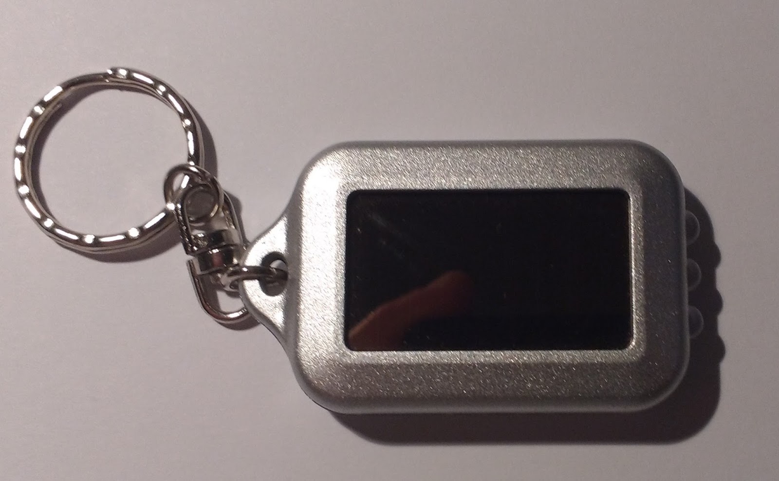
I got this little key ring torch from somewhere I can't remember. I think it cost me a USD or two. It worked well as a torch for a while, but eventually gave up the ghost. It is supposedly solar rechargeable, so lets open it up and see what is on the inside.


The device was glued together, so I couldn't save the enclosure. The inside revealed a very simple circuit. I thought shell was rather well engineered, to good tolerances.


There isn't too much to the electronics, there is a coin cell battery, three LEDs (which I know to be white), a button, and a diode. It is a single sided PCB that is glued a soldered together with a small solar cell panel. There is a mix of through-hole and surface mount components. (The PCB is even has a green solder stop and a white silk screen!)

Lets take a closer look at the components, starting with the battery. I measured the  voltage to 104.5 mV, or 0.1045 V, which means this battery is pretty much dead. The battery was shrink wrapped with solder tabs. Removing the solder tabs and the wrap revealed that this was a Lithium Ion Battery of LIR2032, with a nominal voltage of 3.6V. LIR2032 refers to the battery type, in this case a Lithium Ion Rechargeable and 2032 is its Height and Diameter. So I guess the torch could be rechargeable? Lets dig deeper.


I quickly inspected the (assumed) diode, and measured a forward bias voltage drop of 0.635 V. The diode is there to prevent reverse current into the solar panel, when the panel is not illuminated. Reverse current would damage the panel.


Taking a closer look at the little solar panel, I measured the open circuit voltage to be in the range of 6V under a good desk lamp. I measured the current to be 0.6 mA. The voltage was measured over the now removed battery tabs, and the current across the button. Since the voltage was measured across the solder tabs of the battery, the true voltage of the solar panel is a little higher due to the voltage drop across the diode.


The little button is a surface mount device. Nothing special about that one.

The LEDs mounted on the PCB are of thought hole type, and are white. They are connected in parallel. A typical white LED consumes 20 mA of current at 3.5 V.

Bringing it all together in a nice schematic was simple enough, because of the (extremely) low component count and single sided PCB.

Now, there aren't current limiting resistors for the LEDs, which I guess is to save on component and manufacturing cost. The battery voltage is pretty well matched, but still an LED does not behave according to Ohm's law, so the LEDs could burn out by taking in to much current. (On the other hand, there is a diode to protect the solar panel, So I guess some considerations were made?)

But what really killed this device was the charging circuit. Charging a lithium ion battery requires tight control of the current flowing into the battery, the charging voltage, and the battery temperature. The curve below is for a standard charging characteristics of a LIR2032 battery (0.5 CmA are for normal charge). I guess the solar panel is somewhat within the range, having a current of 0.6 mA and an open circuit voltage of 6 V. There is also no under-voltage or over-voltage protection, meaning you can drain or over-charge the battery to destruction.


In conclusion, it was a mechanical nicely designed little torch. The solar rechargeable aspect of the device is however just a gimmick. I don't think the electronics would do the battery any good, and maybe the thing would have lasted longer had the battery not been connected to the solar panel, and used a standard non-rechargeable battery. Still, it is impressive to get these components (solar panel, rechargeable battery, 3x white LEDs) for 1-2 USD...

Thursday, October 8, 2015

Villavent home HVAC automation

So, it`s still a work in progress, but getting there slowly.

New sensors have arrived, but I'm still waiting for the relays to arrive.

Latest status:

- Two new AM2301 / DHT22 sensors, for better accuracy, precision / repeatability, and resolution.
- Updated GUI to display last 24hr temperatures
- Better display on current air readings.
- Only pulling NTP once per hr
- Some error trapping routines for the wifi, preventing NTP request when wifi is unavailable, and also continously checking wifi status to periodically try to reconnect.

I still have left to:
- Implement control algorithms, which is harder than it looks; multiple input variables and priorities, but only controlling one output (fan speed).
- Maybe adding manual overrides
- Putting the hardware together
- Testing

Monday, September 21, 2015

Villavent HVAC home automation with ESP8266

HVAC controller starting to come together.

So far I have the system connect to wifi and host a web page:
- Reading temperature and humidity data from a DHT sensor
- Fetching time from a NTP server
- Polling at interval (presently 1 min) at interrupt
- Controlling digital outputs

Still waiting on some higher spec sensors to accurately measure intake and outlet air, and some relays to control the fan speed.

Friday, May 23, 2014

Simple Modbus Slave

The idea behind thid project was to experiment a little with the serial bus, to have more than one device on s single serial line, aka multi-dropping.

There are several ways of doing this, but one very common way is using the Modbus protocol. The protocol doesn't specify the eletrical interface. I'm going to use RS485. For processing, I'm going to use an ATMEGA8, since it has hardware USART and I2C. The I2C I'm going to use to interface with the sensor, a LM75 temperature sensor. Other hardware bits are LM7805 linear regulator with a Vmax of 30V and a MAX485 for the serial interface. All components except the block connector are surface mount.

The board was laid out in EagleCAD, which was a first for me. I wanted to learn how to use EagleCAD, since so many other hobbyists do. The board came out nicely, I even added a little silk screen art to the bottom in form of a QR code.


The board outline is 5cmx3.5cm, and double sided. I opted for a 1.6mm PCB thickness for rigidity, and green PCB, white silk-screen and HASL for my wallet. I sent away the design to a PCB prototyping service.

A stack of PCBs arrived at the post office a couple of weeks later. By then I had sourced all the components needed to build the ten boards. Well, there was one component I couldn't source, and that was a the one-way SMT DIP switch. If I make another revision of the board, I will make that one through-hole.

I took me a while to hand solder, as I don't have the equipment to reflow solder. Perhaps it is time to invest in one. Anyway, I think the board turned out well.

As you can see, the 1-way DIP switch is unpopulated. If I make another board revision, that would be one of the things I would change. The QR-code works well thought!

Next up is the code...

Saturday, May 17, 2014

DIY EQ-Dir


It is possible and fairly easy to control Synta telescope mounts (Skywatcher, Celestron, Skytech, and more) from a computer. The most common reason for doing this is to autoguide, which was also my motivation.

The mount interface is a standard serial device, but with TTL levels.  TTL is an abbreviation for Transistor Transistor Levels, and means that a logical 1 = 5 volts and a logical 0 = 0 volts.
Normal serial devices usually work with something like logical 1 = -10 volts and logical 0 = +10 volts, thought there isn't a set standard. (Note: standard serial has inverted logic, on a hardware level a negativ value is logical 1.) If you fed your telescope with these levels you would probably damage the mount controller box, so we need a device that can convert between standard serial levels and TTL levels. This is what An EQ-Dir does, if you've heard that name before.

There are sites that sell these devices ready made, for bluetooth, USB, or a standard serial port, but they are very easy to make yourself, and cheap.

Since none of my current computers have a serial port, I had to find another way interface with my mount. I had two options here: a USB to serial adapter with a sort of TTL converter on the serial end, or a direct USB to TTL adapter. The USB to TTL is actually simpler to make, since the former would require a power supply to drive the TTL adapter.

You can a USB to TTL adapter from ebay, dx.com, or similar. Buy one with a chip from FTDI or Prolific, as these work well for this application. They cost as little as a US dollar including shipping.


The next, and only other, thing you'll need is an ethernet cable you can sacrifice. Cut it to desired length, and strip of a length of the outer insulation.

Only three wires are needed, one each for TX, RX, and signal ground. These are the minimum number of connections for a two-way serial interface. (Note:While researching the solution I came across a few posts that claim you also need to connect the RTS/CTS/DTR/DSR lines, but my mount worked happily without them. I almost never see these lines in use, and I suspect they can be left out on all Synta mounts.)


On the ethernet cable, it is the midle pins that are in use (4,5 & 6).


Connect as marked on the adapter, where 4 goes to  GND, 5 to TX, and 6 to RX. The colours on the wires in the ethernet cable are normally blue (4), blue/white (5), and green (6).

That's it. The rest is all software.

Saturday, November 30, 2013

Thesis

Well, the thesis was handed in this summer, and I'm now a Master. I didn't post my progress, simply because It was a mad bussy time.

I may post some of the main results, but at the moment I'd like to do something completely different...