Showing posts with label teardown. Show all posts

Monday, January 23, 2017

Resurecting a internet tablet (Eken M001) - Dead battery

So, I've had this internet tablet for a while now. I bought it cheap, in the early years of the tablet revolution. It's been sitting on my shelf unused, as it couldn't compete with 1.gen Ipad.

 
A little while ago I tried to turn it on again, to be used in a project idea I have. However, it had given up the ghost. After opening the case and inspecting it, it turned out that the battery was completely dead. Zero volts over the cells, and the balancing board corroded beyond recognition!


Turns out, a suitable battery was expensive, more expensive than I was willing to spend on this project. I thought, therefore, I could hack an inexpensive RC pack. So I bought got hold of an RC pack and a new balancing/protection board.


After peeling everything (carefully) apart (because they can explode), I de-soldered the cells free. If you attempt this, please take appropriate safety precautions. I then soldered the cells onto the protection board, and applied copious amounts of capton tape.


To get the protection board working (activation), a charging current needs to be applied. Otherwise no voltage will appear across the load output. (This needs to be done every time the cells are disconnected from the board). The simplest solution it to connect the new battery to the tablet.


I had to reflash the tablet with firm ware, probably because of the prolonged powerloss.


And then everything worked perfectly! Battery reading and everything!! Well chuffed :) I reckon there is about an hours use on full screen brightness. Not a huge amount, but for what I'm going to use it for, it doesn't matter anyway.


Friday, November 4, 2016

What's inside a really expensive LED lamp light

I bought these really expensive LED lamp light for our new outdoors night lights. They even came with a 2 year warranty. I plashed out on these LED based lights, because:
  1. They use less energy, hence are more environmentally friendly.
  2. They last (supposedly) longer, hence are cheaper in the long run and are, because of this, more environmentally friendly as fewer materials are consumed.
 As a foot note, do not replace working lamps (incandescent or fluorescent) until they eventually burn out.


Since they failed in little over a year, I thought I'd do a postmortem on one of them.

The top is also a lens cover, and it came off easily despite being glued on, revealing the LED circuit board.


The circuit board substrate is metallic, and the board is thermally connected to a pretty hefty lump of metal with some white thermal paste, most likely silicone based. It is probably there to dissipate heat from the LEDs, or maybe give the lamp that "premium" feeling weight.


Now, removing the heat-sink and LED board reveals a second circuit board. Cutting of the mains legs frees the second circuit board.


The second circuit board is a relatively simple thing, a single sided PCB with a handful of components. There is a mix of surface mount and through whole components. Looking at this second PCB I feel a little disappointing, as this is where I would expect my very expensive LED lamp to distinguish itself from any cheap LED lamp, but at first glance it is a really simple passive circuit!


This second circuit board is just a simple diode bridge rectifier, with a few additional passive components thrown in the mix. On the AC input side are two resistors and a capacitor: 33 Ohm / 1 W, 1M Ohm / 0.25W, and a 0.90uF / 400V film capacitor. On the DC side there is one 2.2 uF / 400V polarized capacitor and a 300k Ohm SMD resistor. The diodes used are marked M7, which is a general rectifier diode rated for 1 A / 1000 V. I have 220V / 50Hz AC in my house, so straight of the rectifier bridge there will be a very rough 220V "DC".  I've not reverse engineered the circuit, but I'm assuming something is being done to lower the DC voltage, because the LEDs would not be able to take 220V.

The LEDs are "Natural" white 2835 SMD LEDs, which have a forward voltage of 3.2 V and 60 mA continuous forward current. There are nine of them in a straight series. This means the ideal DC voltage is 28.8 V.

I've traced the LED circuit to bring out the serially connected LEDs.


So there you have it. Certainly not worth the premium price, and since they lasted a shorter time than a normal incandescent equivalent, this is a definitive "Do not buy!".

Thursday, July 21, 2016

Solar Rechargeable Pocket Flashlight Teardown

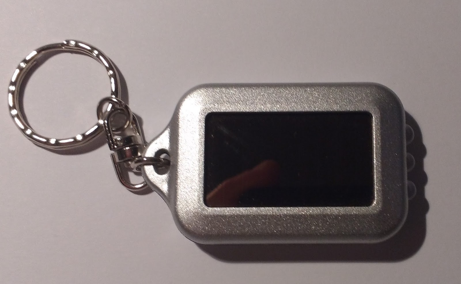
I got this little key ring torch from somewhere I can't remember. I think it cost me a USD or two. It worked well as a torch for a while, but eventually gave up the ghost. It is supposedly solar rechargeable, so lets open it up and see what is on the inside.


The device was glued together, so I couldn't save the enclosure. The inside revealed a very simple circuit. I thought shell was rather well engineered, to good tolerances.


There isn't too much to the electronics, there is a coin cell battery, three LEDs (which I know to be white), a button, and a diode. It is a single sided PCB that is glued a soldered together with a small solar cell panel. There is a mix of through-hole and surface mount components. (The PCB is even has a green solder stop and a white silk screen!)

Lets take a closer look at the components, starting with the battery. I measured the  voltage to 104.5 mV, or 0.1045 V, which means this battery is pretty much dead. The battery was shrink wrapped with solder tabs. Removing the solder tabs and the wrap revealed that this was a Lithium Ion Battery of LIR2032, with a nominal voltage of 3.6V. LIR2032 refers to the battery type, in this case a Lithium Ion Rechargeable and 2032 is its Height and Diameter. So I guess the torch could be rechargeable? Lets dig deeper.


I quickly inspected the (assumed) diode, and measured a forward bias voltage drop of 0.635 V. The diode is there to prevent reverse current into the solar panel, when the panel is not illuminated. Reverse current would damage the panel.


Taking a closer look at the little solar panel, I measured the open circuit voltage to be in the range of 6V under a good desk lamp. I measured the current to be 0.6 mA. The voltage was measured over the now removed battery tabs, and the current across the button. Since the voltage was measured across the solder tabs of the battery, the true voltage of the solar panel is a little higher due to the voltage drop across the diode.


The little button is a surface mount device. Nothing special about that one.

The LEDs mounted on the PCB are of thought hole type, and are white. They are connected in parallel. A typical white LED consumes 20 mA of current at 3.5 V.

Bringing it all together in a nice schematic was simple enough, because of the (extremely) low component count and single sided PCB.

Now, there aren't current limiting resistors for the LEDs, which I guess is to save on component and manufacturing cost. The battery voltage is pretty well matched, but still an LED does not behave according to Ohm's law, so the LEDs could burn out by taking in to much current. (On the other hand, there is a diode to protect the solar panel, So I guess some considerations were made?)

But what really killed this device was the charging circuit. Charging a lithium ion battery requires tight control of the current flowing into the battery, the charging voltage, and the battery temperature. The curve below is for a standard charging characteristics of a LIR2032 battery (0.5 CmA are for normal charge). I guess the solar panel is somewhat within the range, having a current of 0.6 mA and an open circuit voltage of 6 V. There is also no under-voltage or over-voltage protection, meaning you can drain or over-charge the battery to destruction.


In conclusion, it was a mechanical nicely designed little torch. The solar rechargeable aspect of the device is however just a gimmick. I don't think the electronics would do the battery any good, and maybe the thing would have lasted longer had the battery not been connected to the solar panel, and used a standard non-rechargeable battery. Still, it is impressive to get these components (solar panel, rechargeable battery, 3x white LEDs) for 1-2 USD...